VALSpring by Valrom provides complete solutions for water abstraction from wells, including PVC pipes, fittings, and specialized chambers. The system is complemented by filters and submersible pumps that ensure a constant flow rate and effective protection against impurities. Valrom technology optimizes the water filtration and conveyance process, making it ideal for residential, agricultural, and industrial applications.
Products VALSpring




VALROM · VALSPRING
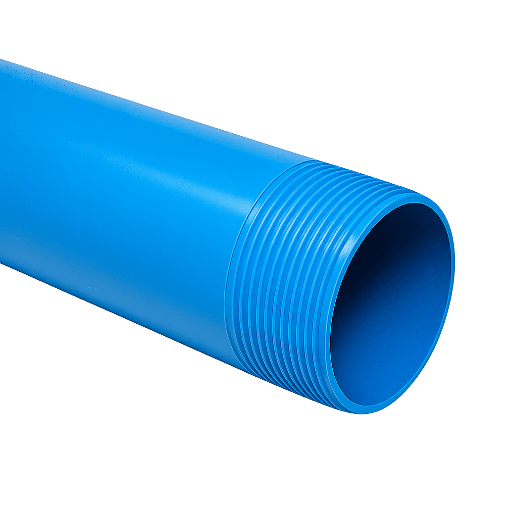
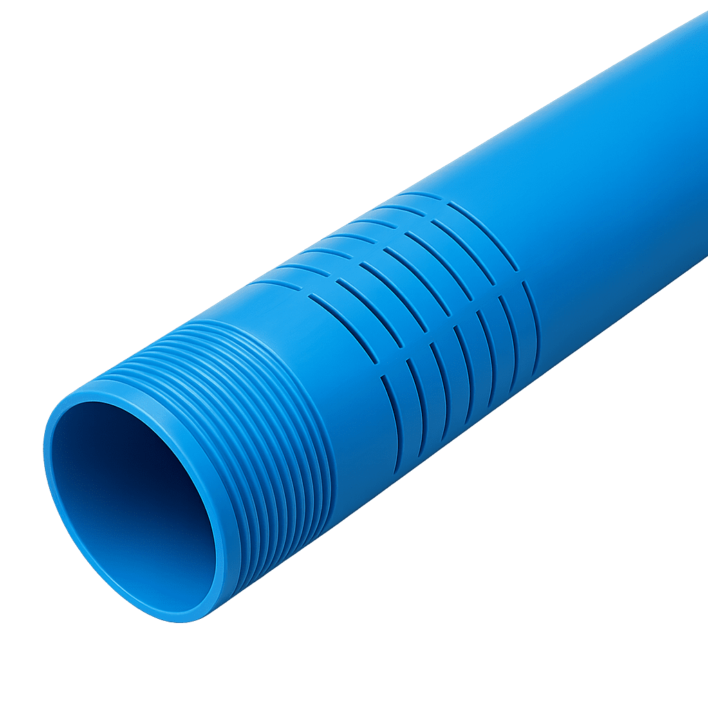
Pipes and fittings for well casing
VALSpring products, manufactured by Valrom, are designed for constructing groundwater catchment wells, for drinking-water treatment or industrial use. The VALSpring system comprises casing pipes, filter (screen) pipes and accessories, made entirely of unplasticized PVC (PVC-U). They meet the most demanding quality requirements in the field while remaining cost-effective.
The outstanding properties of unplasticized PVC make it the ideal material for this type of application:
PVC-U
Chemical properties
The chemical resistance of PVC-U piping is remarkable. Buried pipes withstand, over the long term, groundwater of every category — including seawater or brine — and even dilute acid or alkaline solutions. Repeated use of cleaning or disinfecting agents does not affect the chemical stability and, consequently, the mechanical stability of the buried piping.
In addition, PVC-U releases no toxic compounds into water and is universally accepted for use in drinking-water transport and distribution networks.
PVC-U
Physical properties
The main physical properties of the material used to manufacture the VALSpring system components are shown in the table below:
| Characteristic | Unit | Value | Testing method |
|---|---|---|---|
| Elasticity modulus | N/mm² | 2500 ÷ 3000 | EN ISO 178 |
| Impact resistance | — | no breaks | EN ISO 179 |
| Density | g/cm³ | 1.4 | DIN 53479 |
| Vicat softening point | °C | 80 | EN ISO 306 |
| Tensile strength | N/mm² | 45 ÷ 50 | EN ISO 527-2 |
| Elongation at break | % | ≤ 10 | EN ISO 6258-2 |
Technical documentation
Recommendations and instructions
Recommendations for constructing wells with VALSpring PVC casing
General rules
We recommend that the maximum depth of a well cased with PVC pipes and screens does not exceed:
- 45 m — for wall-thickness class R8
- 90 m — for wall-thickness class R10
- 300 m — for wall-thickness class R16
In addition, during borehole equipping and cleaning and during operation, the level difference “h” between the liquid level inside the pipe and the liquid level (water, water–bentonite–mud mix, etc.) outside the pipe must not be exceeded:
- h = 15 m — for wall-thickness class R8
- h = 30 m — for wall-thickness class R10
- h = 120 m — for wall-thickness class R16
When casing the well with VALSpring PVC-U pipework, Valrom Industrie SRL recommends:
- The difference between the diameter of the drilled borehole and the diameter of the PVC casing pipe must be at least 150 mm.
- Gravel packing with pearl gravel must be carried out counter-current, by feeding water into the PVC pipe while the gravel is poured; the gravel must be added gradually and in small quantities.
- Joining pipework of different wall-thickness classes is not permitted under any circumstances. A well of a given depth must be cased entirely with pipe of the wall thickness recommended for the well’s maximum depth.
- Before inserting the pipes into the borehole, carefully check their integrity and clean the threads of any impurities, to avoid introducing additional stress into the threaded joint.
- For threading and handling the PVC pipes, use only tools and equipment that do not damage the pipe (with the parts contacting the PVC pipe or screen made of rubber).
- During well-development (clearing) work, monitor the water level in the well so that the difference between the water level in the mud pit and in the well does not exceed the permissible level difference “h”.
Equipping the well with a submersible pump
- Maintain the clearance defined by the difference between the pump’s maximum outer diameter and the inner diameter of the PVC pipe or screen, as recommended by the pump manufacturer.
- The flow drawn by the pump from the well must be lower than or at most equal to the well’s yield, as stated in the well hand-over report.
- The pump must be fitted with a soft starter or a frequency converter, to avoid start-up surges.
- The pump must be fitted with thermal protection.
- The well must be fitted with level-sensor automation that stops the pump when there is no water.
Transport, storage and handling
Transport
During transport, the PVC pipes must be supported along their entire length, to avoid damaging the ends through vibration. Avoid impacts, bending, excessive overhang beyond the supporting platform, and contact with sharp and/or cutting objects.
Load-securing straps may be made of rope or webbing in hemp, nylon or similar materials; if steel cables or straps are used, the pipes must be protected at the contact areas. Stacked pipes are arranged with the socket toward the end of the stack so that the socket does not damage them; where necessary, special spacers are used between pipes.
When loading, place the heavier pipes first to avoid damaging the lighter ones. For road transport, the pipes should not overhang the loading platform by more than 1 m. When moving on site, dragging the pipes along the ground is not recommended, as it can damage them irreparably.
Loading and unloading
Loading and unloading operations must be carried out with great care for all materials and/or products. The pipes must not be thrown or dragged to the edges of the vehicles, but lifted and supported carefully. If these rules are not followed, breaks or cracks may occur, especially in winter at low temperatures.
Storage
PVC pipes and screens for well casing must be stored on smooth surfaces, free of sharp parts and substances that could damage them. Socketed pipes are stacked on wooden battens so that the sockets are not deformed; when palletizing socketed bundles, the sockets are placed alternately on either side of the bundle, projecting outward, so that they bear no load and the pipes rest along their full length.
Pipes must not be stored at a height greater than 1.5 m, to avoid deformation over time. If not used for a long period, protect them from sunlight without preventing ventilation. When shipped in frame-bound bundles, follow the manufacturer’s instructions for stacking.
On sites where the ambient temperature may exceed 25 °C for an extended period, avoid storing the pipes in more than two stacked bundles, to prevent ovalization of the pipes in the lower layers. At low temperatures the likelihood of PVC pipes breaking increases; in such conditions, transport, storage and installation operations must be carried out with great care.
Accessories
Accessories are generally delivered in special packaging. If unpackaged, avoid storing them in disorder during storage and transport, and prevent damage from collisions with one another or with other heavy materials.
Warranty
The product warranty is granted only if the above recommendations are observed.
VALSpring
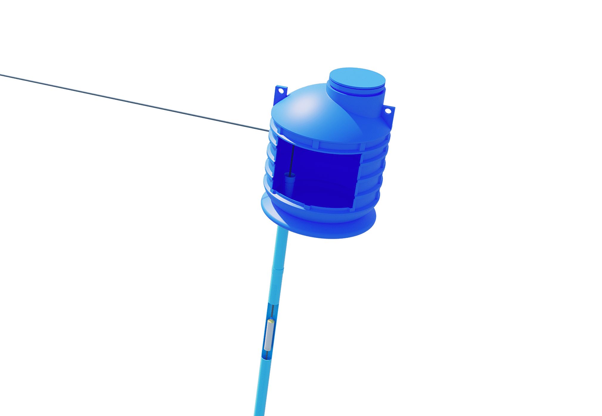
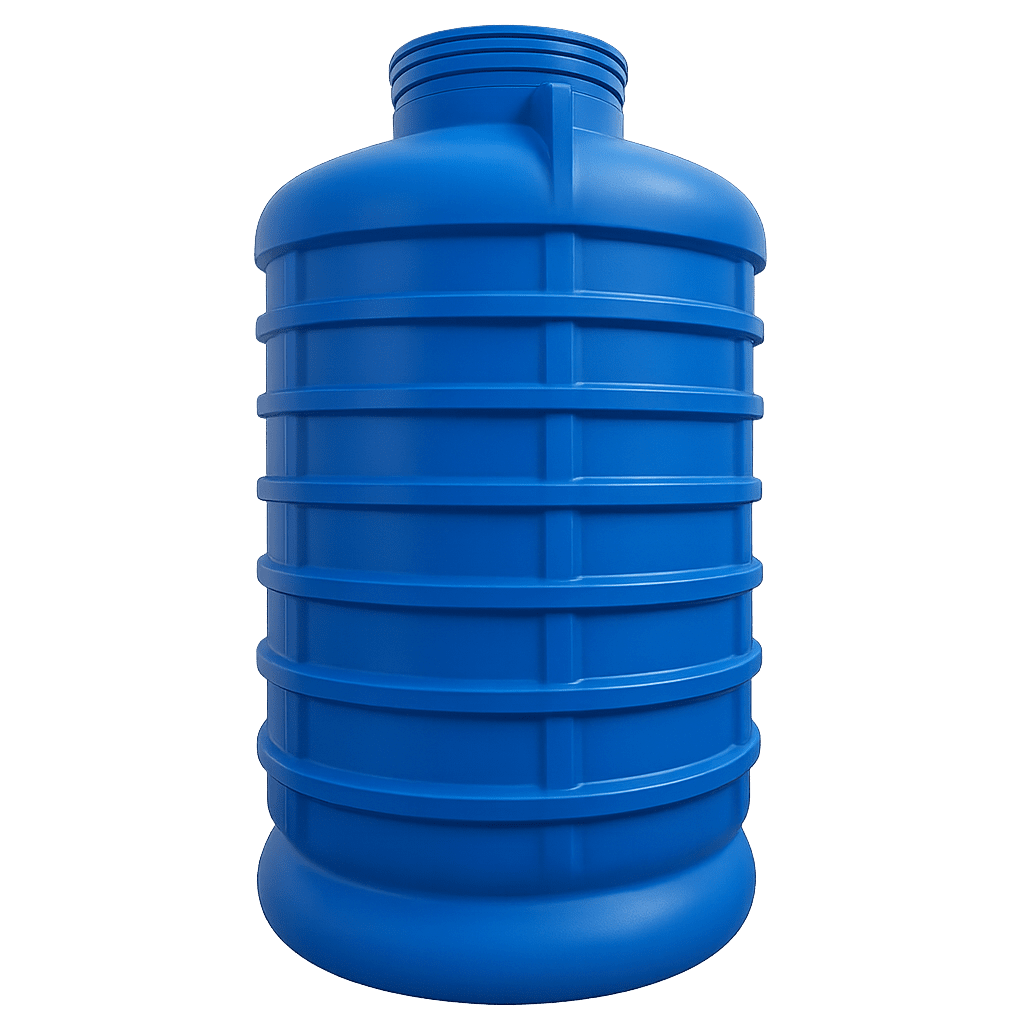
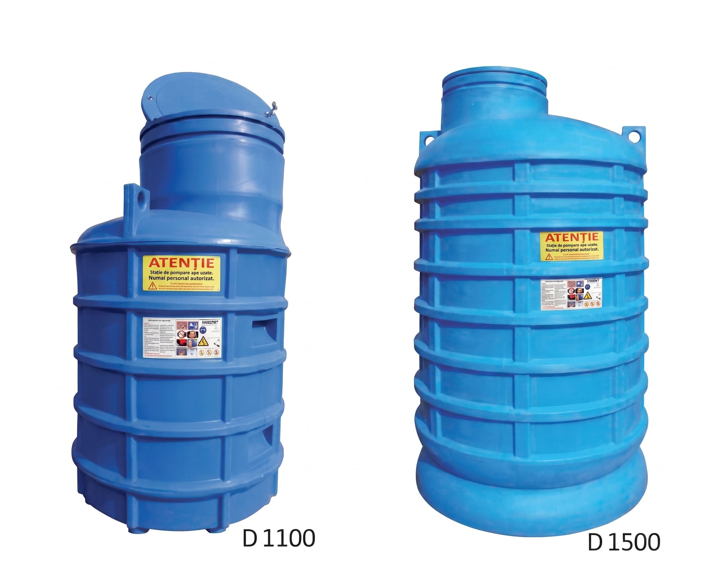
Water-well cabin with cover and locking system
The well cabin protects the fittings (and possibly other components: expansion vessel, filters, etc.) required to supply a home with water from the well.
For connecting the well pipe, the bottom of the chamber has a flat circular area, coaxial with its opening, of diameter D = 300 mm, where the hole for the well pipe is made, with a maximum diameter of Ø250 mm. A Ø6 mm hole is factory-provided at the centre of the flat area. Sealing between the chamber wall and the well pipe is achieved with a gasket (optional product).
The locking system consists of two locks placed diametrically opposite on the cover and an operating key.
Installing the well cabins
- 1
Mark the cabin installation area according to the well position. The well pipe will pass through a flat circular area (concentric with the cabin access area), whose centre is identified by a Ø6 mm hole in the cabin base.
- 2
Dig the installation pit at the well. The distance between the cabin and the wall must be at least 30–40 cm, needed to introduce the compaction equipment. The pit depth must account for the slab thickness. The bottom of the pit must be flat.
- 3
Lay the sand bed or the reinforced-concrete slab, depending on the designed/adopted solution, the cabin size and the soil stability.
Caution!
- In clayey soils, regardless of size, the cabin must be installed on a reinforced-concrete slab.
- Regardless of soil type, DN1500 cabins must be installed on a reinforced-concrete slab.
- 4
Prepare the cabin. Drill the well-pipe access area with a core bit and seal it with a gasket. To ease installation, lubricate the gasket with a silicone-based lubricant and chamfer the well pipe at 15°. Do NOT use mineral oils or greases. Make sure the gasket and the well pipe are clean at the installation areas (free of sand, gravel, rubble, etc.) — sealing reliability depends on this.
- 5
The cabins are handled with on-site machinery or lifting devices (e.g. a crane). Place the cabin carefully so that the pipe passing through the connection gasket is not compromised. The final position of the cabin must be stable.
- 6
Using a suitable core bit/cutter, make the pass-throughs in the cabin for connection to the water installation. Fit the gasket, route the supply pipe and direct it toward the home/application through the trench.
Caution!
Pass-throughs must be made through the flat surfaces, not on a rib; maximum pass-through diameter D125 mm.
Fit the cable gland for the equipment power cable and route the connection cable.
- 7
Cover with the lid.
- 8
Fill the space between the cabin and the pit walls with layers of about 25–30 cm of backfill — sand or soil free of stones, rubble or other protruding particles that could scratch the chamber walls. Particular attention is given to the supply-pipe areas, where the backfill must be sand, in 15 cm layers above and below the pipes. Each layer is carefully compacted to the Proctor compaction degree appropriate to the ground, at least 95%, so that the entire space around the cabin is filled.
Caution!
- In clayey soils, build a drainage system around the cabin from pipe and draining material — gravel of 20–30 mm grain size; the final covering layer may be clay or topsoil.
- If the water table is shallow (above the cabin base), place the cabin on a concrete foundation sized according to the hydrogeological and static conditions of the ground (thickness must match the substrate strength) and concrete it partially or fully, depending on the groundwater level. When concreting, to balance the pressure of the poured concrete on the walls, support the cabin internally with a batten; pour in layers of about 30 cm. Before pouring, lower the water level by pumping below the concrete slab.
When fitting equipment, insulation and ventilation of the cabin may be required. Mind the equipment’s installation and operating conditions. Do not forget to install the power-supply cable — it can be introduced into the cabin through a suitable cable gland.
Installation of the cabin and the system must comply with the occupational-safety regulations in force.
Need the technical datasheet or expert advice?
The Valrom team helps you with specifications, sizing, and selecting the installation technology best suited to your project.