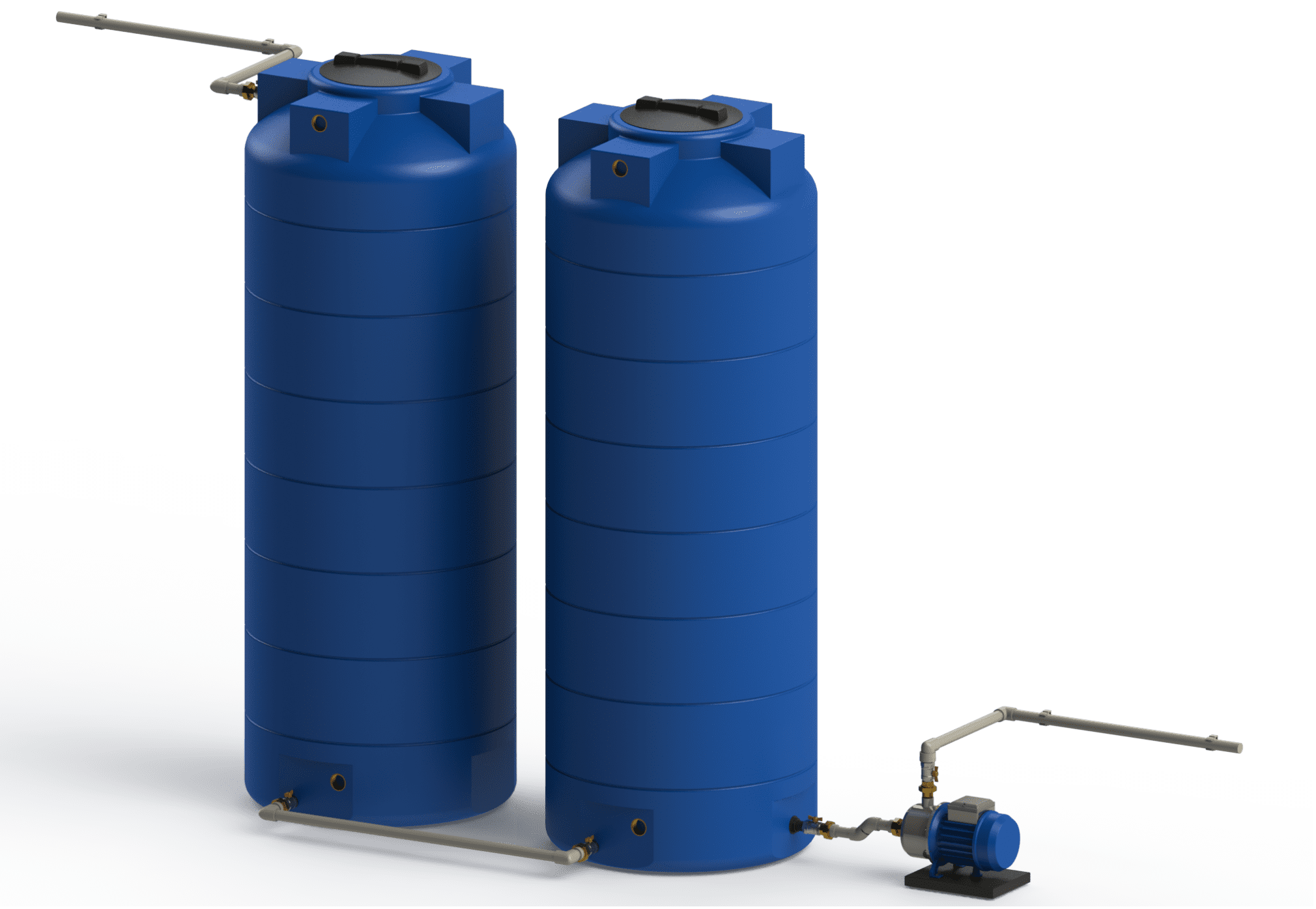
VALStock by Valrom offers a complete system of tanks, pumps, and accessories for efficient water storage, filtration, and use. The solutions are designed for residential, agricultural, and industrial applications, contributing to optimal consumption and sustainable water resource management. VALStock systems are ideal for water supply, irrigation, or technical reserves, providing durability and efficiency in any environment.

Products VALStock

Daily comfort with VALStock tanks

VALStock solutions ensure a constant water reserve for homes, guesthouses, or farms, regardless of network fluctuations or drought periods. Above-ground and underground tanks, together with dedicated pumps and accessories, enable water supply at optimal pressure for household consumption, irrigation, or yard/car washing, reducing the risk of interruptions and optimizing resource consumption.

100% virgin raw material for safe water storage

VALStock tanks are made from high-quality materials, 100% virgin raw material, resistant to corrosion and contact with drinking water, rainwater, or process water. The monolithic construction, without welds, and walls with optimized thickness ensure rigidity, watertightness, and long service life, while the extensive range of volumes and shapes (horizontal, vertical, underground, metal panel) allows the system to be adapted to any type of application—from residential to industrial.

Installation instructions — above-ground tanks

VALROM · STOCKKIT

INSTALLATION INSTRUCTIONS — ABOVE-GROUND TANKS

The tanks are designed for above-ground, floor-standing installation, at atmospheric pressure and fluid temperatures in the 5 ÷ 45 °C range, mainly for storing drinking water. Other permitted applications: storing rainwater, irrigation water or food-grade liquids (oil, milk).

VALROM above-ground tank
Above-ground tank

Rules for the use and installation of above-ground tanks

Note

  • The tanks must NOT be used at pressures below or above normal atmospheric pressure (they cannot be used for pressurized or vacuum storage).
  • The tanks must NOT be used for fuels or other petroleum products, nor for chemically aggressive substances (acids, bases, etc.).

Installation must be carried out by qualified persons, in compliance with the regulations in force, including Romanian occupational-safety rules, and with these instructions.

The tank installation area must be large enough to allow installation, handling and maintenance. The surface on which it is installed must be firm and even, able to support the weight of the full tank. We recommend installing the tanks in technical rooms with low humidity, not exposed to UV radiation or frost.

When installed in high-humidity spaces there is a risk of condensation; in such cases, the tank must be insulated.

Before installing the tank and its associated system, check the following:

  • The tank surface must be free of defects visible to the naked eye or of deformations that could affect functionality (inclusions, scratches, cracks or peeling layers).
  • The tank must be empty, clean and watertight (no visible signs of transport damage).

If the tank is used as a buffer tank, it is mandatory to:

  • install the tank only in a technical room that is mandatorily fitted with a floor drain;
  • fit an overflow on the tank, connected to the sewer, to prevent — in the event of a feed shut-off failure — the tank being subjected to pressure above the normal operating pressure;
  • fit the air vent valve on the lid.

To connect the tank to installations you can use the internally-threaded brass inserts pre-mounted on the tank (data available in the StockKIT catalogue and in the tanks’ technical specifications), or fit a nipple–nut kit on a flat area of the tank (the kit is supplied on request).

Using the brass inserts provided on the tank

Drilling the metal insert pre-mounted on the tank must be done only with suitable cutters/hole saws. While drilling, the cutter must not touch the thread.

Connecting the tank through this metal insert must be done ONLY with a flexible pipe/hose, to avoid stressing the tank walls during liquid filling/emptying.

The threaded joint must be sealed ONLY with Teflon® (PTFE) tape. Do NOT use hemp packing or sealing liquid/paste.

Installing the nipple–nut kit

The nipple–nut kit is installed only on perfectly flat areas of the tanks. Sealing between the kit and the tank walls is achieved with gaskets.

Available sizes for the nipple–nut kit:

1″1″ 1/41″ 1/22″2″ 1/2

Gaskets for installing the kit:

  • gaskets for the FE connector — 2 gaskets required for installation; they seal inside and outside against the tank wall;
  • gasket for the FI plug — 1 gasket required for installation, when the plug is used to close off the connector.

Caution!

Gaskets are ordered separately!

The order of the parts at installation is as shown in the diagram.

For installing the kit you need: a marker pencil, a tape measure, a power drill with a cutter and a cutter knife. The correspondence between cutter sizes and kit sizes is as follows:

Kit — d [″]Cutter — D [mm]
1″33
1″ 1/443
1″ 1/248
2″59
2″ 1/275
Assembly diagram — nipple–nut kit

Kit installation steps

1Mark the centre of the hole.
Mark the centre of the hole.
2Drill with the power drill and the appropriate cutter.
Drill with the power drill and the appropriate cutter.
3Deburr.
Deburr.
4Fitting the nipple: place one FE gasket on the nipple, then insert the nipple into the drilled hole from inside the tank; place the second FE gasket on the nipple thread, then the nut, and tighten gently.
Fitting the nipple: place one FE gasket on the nipple, then insert the nipple into the drilled hole from inside the tank; place the second FE gasket on the nipple thread, then the nut, and tighten gently.
5Tightening the nut.
Tightening the nut.
6Kit installed.
Kit installed.

Connecting the tank via the nipple–nut kit to a polyethylene-pipe installation

For the connection you need: Teflon tape, an FE compression fitting matching the kit size, and a polyethylene pipe of the matching size.

Make the connection following these steps:

  • Prepare the nipple, wrapped with Teflon tape.
  • Fit the compression fitting onto the prepared nipple and connect the polyethylene pipe, following the installation instructions for compression fittings (the ones found at VALWater), as follows:
  • unscrew the blue nut on the fitting by 3–4 turns;
  • measure and mark how far the pipe must enter the fitting, so that it passes the O-ring and reaches the inner shoulder;
  • insert the pipe into the fitting up to the mark; note: the pipe must have clean, straight edges, preferably chamfered, so it does not catch the gasket;
  • tighten the nut depending on the size: by hand (OD 20, 25, 32) or with the compression-fitting wrench (40, 50, 63, 75).
Connection with compression fitting

Installing the air vent valve

The air valve for water tanks allows air to enter or escape in order to maintain atmospheric pressure, regardless of the fluctuations in the liquid level inside the tank. For installation you need: a power drill with a D32 cutter and a cutter knife. The valve is installed on the tank lid, following the steps in the images:

1Air vent valve.
Air vent valve.
2Drill a hole in the lid with a 32 mm cutter.
Drill a hole in the lid with a 32 mm cutter.
3Deburr the edges of the hole.
Deburr the edges of the hole.
4Insert the valve into the created opening.
Insert the valve into the created opening.

Commissioning

Before use, polyethylene tanks must be ventilated for 24 hours and then washed with water and detergent.

Maintenance: check the tank periodically and, in case of deposits, wash it with a pressurized water jet and/or with water and dish detergent, using a soft sponge.

Spare parts for above-ground tanks

Lids and gaskets can be supplied on request. Lid dimensions are specified in the Valrom documentation and in the tanks’ technical specifications.

Need the technical datasheet or expert advice?

The Valrom team helps you with specifications, sizing, and selecting the installation technology best suited to your project.